The KS4400 series is simple, modular and flexible yet highly functional. The half shell design is cost effective and provides exceptional space utilization. Three levels of terminals with fixed and pluggable PCB terminal options allow for high density connections. A large front face area provides ample space for operator, communication and visual display components.
MATERIALS
Housing
Housing Shell: Polyamide, Glass Filled; Front Plate: PBT
Terminals
Housing: Polyamide; Terminal Pins: Tinned Brass
Temperature Range: 120°C (248°F) UL94V0
Standard Color:
Black Housing with Gray Front Plate. Other colors are available upon request.
PROTECTION
KS4400 enclosures have an IP40 rating, IP20 for terminal openings (finger protected) and meet VBG4 and other European accident prevention requirements.
CONSTRUCTION
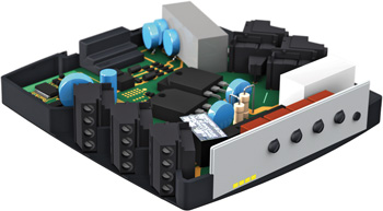
The KS4400 enclosure series housings are supplied as unassembled kits. Each kit consists of two half shells, a front plate, DIN rail clip and terminal sets. The terminals are set on three levels to maximize space. The terminals are machine solderable with right angle pins. PC boards are mounted vertically in the enclosure, perpendicular to the DIN rail.
TERMINALS
The terminals are available as fixed or pluggable PCB terminals. The terminal blocks are all machine solderable. Fixed PCB terminals are standard screw cage clamp style terminal blocks.
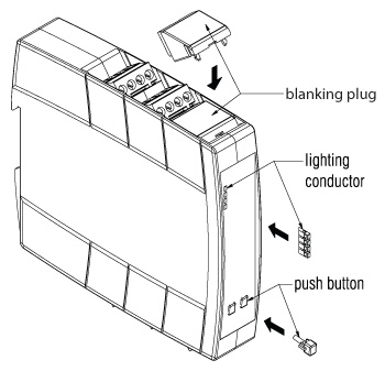
Pluggable PCB terminals feature male pin headers and female screw cage clamp or spring cage clamp plugs that can be plugged/unplugged. Terminal spaces can also be left blank and covered with a snap in cover (terminal blanking plug).
MOUNTING
The KS4400 series can easily be mounted on standard 35mm DIN rail by means of the integral mounting foot and DIN clip.
MARKING
The KS4400 series have large marking areas on the front of the cover.
CUSTOMIZATION
We can supply the KS4400 series enclosures with many custom options including:
- Partial or mixed terminal loading
- Printing/Marking
- Enclosure bus connections
- Ventilation Slots
- Machining of custom holes
- Hinged front covers
- Front cover with test buttons
ASSEMBLY OF ENCLOSURE
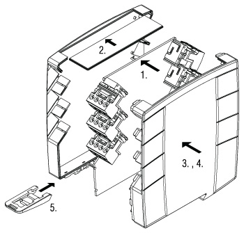
- With terminals fitted, place the PCB in the first enclosure half shell.
- Slide the front plate in the slot in the first enclosure half shell.
- Place this assembly flat and line-up the second half shell so that the front plate slides into the slot.
- Manually close both half shells until they snap together.
- Insert the DIN rail mounting clip into the base of the enclosure.

ACCESSORIES AND OPTIONS

Application Example

|

