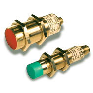
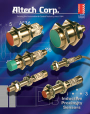
CYLINDRICAL INDUCTIVE PROXIMITY SENSORS
Altech Cylindrical sensors are available in diameters ranging from 8mm (.32 in.) to 30mm (1.18 in.) with sensing distances up to 15mm (0.59 in.). Most models feature nickel plated brass (BN) and stainless steel (SS). Both flush mount and non-flush mount sensors are available. Non-flush sensors have larger sensing distances than their flush mount counterparts. All Inductive sensors meet IP67 (NEMA1, 3, 4, 6, 12, 13) protection levels.
FLUSH MOUNT CYLINDRICAL SENSORS
Flush Mounted, sometimes called embedded or shielded sensors, have electromagnetic fields concentrated directly in front of the sensing heads and may be mounted directly onto metal mounting brackets or embedded directly into metal without causing a false output. Figure 8 (located on page 7) also illustrates that on Cylindrical Flush Mount sensors there should be at least 1 diameter of distance between adjacent sensors, and no non-target metal surfaces should be less than 3 times the sensing distance Sn directly across from the sensing head. Also, two directly opposite sensors mounted in metal should be greater than 6 times the sensing distance apart.
NON-FLUSH CYLINDRICAL SENSORS
Sometimes called non-embedded or non-shielded, non-flush sensors have electromagnetic fields with a wide sensing angle and are unshielded (no metal surrounding the sensing head). Care must be taken to insure that no non-target metal comes in near proximity to the sensing head. Distances are demonstrated in Figure 8. Adjacent sensors should be separated by at least 2 times the diameter. Non-target metal should be at least 3 times the sensing distance directly across from the sensing head. Two directly opposite sensors should be at least 6 times the sensing distance apart.
OUTPUT CONNECTIONS
AC,DC – Normally Open (NO),
and Normally Closed (NC).
DC – Complementary output (NO/NC) available on some models.
OUTPUT CABLES
Cylindrical Sensors are provided with
2 meter PVC fixed cables. 5 meter PVC,
2 and 5 meter PUR cables are optional. Consult Altech for more information.
QUICK DISCONNECT
CONNECTORS
Altech sensors are available in a wide selection of Quick Disconnect styles for DC circuits. Virtually any sensor can be custom manufactured with a Quick Disconnect connector. Consult Altech for more information.
Quick Disconnect models are designed to be user-friendly and to simplify installation.
Please see the product specification for sensors with quick disconnect connectors and matching cable assemblies on pages 26-31 in the accessory section.
HOUSING MATERIALS
AC – Nickel Plated Brass
DC – Nickel Plated Brass
Stainless Steel
TIP MATERIAL
PBTB – Polybutelyne Terephthalate
INTRODUCTION
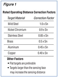
The Inductive Proximity Sensor (IPS) is a solid state device that generates an output signal when metal objects are either inside or entering into its sensing area from any direction. No physical contact is required nor desired. IPS's work best with ferrous metals, however, they also work well with non-ferrous metals (aluminum, brass, copper, etc.) at reduced sensing distances, see Figure 1.
First introduced in the mid 60’s, Inductive Proximity Sensors were designed as an alternative to mechanical limit switches for many applications. Initially, IPS's were made with housings similar in size and dimension to the limit switch, but had short sensing distances. Following very good results with these new devices, market pressure led to the development of larger sensors with increased sensing distances.
Inductive Proximity Sensors have no moving parts, operate very fast, are extremely reliable, require no maintenance and operate under extreme environmental conditions.
They typically interface with Programmable Logic Controllers (PLC) and personal computers with appropriate hardware and software. They also control relays, solenoids, valves, etc., up to their maximum output current.
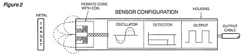
An Inductive Proximity Sensor consists of an oscillator, a ferrite core with coil, a detector circuit, an output circuit, housing, and a cable or connector; see Figure 2. The oscillator generates a sine wave of a fixed frequency. This signal is used to drive the coil. The coil in conjunction with the ferrite core induces an electromagnetic field. When the field lines are interrupted by a metal object, the oscillator voltage is reduced proportional to the size and distance of the object from the coil. The reduction in the oscillator voltage is caused by eddy currents induced in the metal interrupting the field lines. This reduction in voltage of the oscillator is detected by the detecting circuit. In standard sensors, when the oscillator voltage drops below a present level, an output signal is generated.
OPERATING VOLTAGES
Most Altech Inductive Proximity Sensors are available in DC (10-30. VDC), AC (90-250VAC). Please refer to each product specification page for specific operating voltages.
OUTPUT CURRENT
Altech offers a range of IPS's with different output ratings from 5mA to 500mA. Please refer to each product specification page for specific output current.
OUTPUT CONFIGURATION
Outputs may be Normally Open (NO) or Normally Closed (NC).
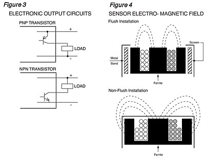
DC Inductive Proximity Sensors are 3-wire. A 3 -wire DC sensor can be a NPN or PNP output transistor. If the output load is connected to the negative power source then a sensor with a PNP output transistor is required. A PNP sensor is also known as a source sensor. If the output load is connected to the positive power source, then a sensor with a NPN output transistor is required. A NPN sensor is also known as a sink sensor. Please see Figure 3 for PNP and NPN electronic output circuits. AC Inductive Proximity Sensors are 2-wire devices, except when using a sensor with a metal housing where a third wire is available for connection to system ground.
HOUSING MATERIALS
Altech Inductive Proximity Sensors use a variety of metallic housing materials. Please refer to each product specification for specific information on housing materials.
CONNECTIONS
Altech offers Inductive Proximity Sensors that feature either 2 meter fixed PVC cable or a variety of quick disconnects. All quick disconnect models require an optional matching cable assembly. Custom cable lengths and material choices are also available. For more information, please refer to each product specification or the cable assemblies section on page 26-31.
FLUSH MOUNT AND
NON-FLUSH MOUNT
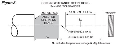
Flush Mount sensors are sometimes called Shielded or Embedded. A metal band surrounds the sensing head which contains a coil wound around a ferrite core as in Figure 4.
The resulting electromagnetic field is directed in front of the sensor face. Flush sensors have a narrow sensing field which may be desirable in certain applications. In a Non-Flush (Non-shielded or Non-embedded) sensor; Figure 4, there is no metal band and the resulting electromagnetic field lines are much wider than the sensor face. Non-Flush sensors have a larger sensing distance than Flush sensors.
OTHER CONSIDERATIONS:
SENSORS IN SERIES
AND PARALLEL
Sensors may be wired in series or parallel.
PROTECTION (Electrical)
Most of the Inductive Proximity Sensors Altech offers have short circuit, overload, reverse polarity, and wire break protection. Please refer to the Technical Glossary pages 32-33 and the product specification for more information.
PROTECTION (Sensor Housing)
All Altech sensors are rated in accordance with IEC Publication 529, which describes degrees of protection that enclosures or sensor housings are designed to provide, the degree of protection is indicated by two letters (IP) and two numerals for additional information see the product specification and page 34.
All Inductive sensors meet the following shock and vibration requirements: 30g’s/11ms, and 10-55 Hz/mm.
SENSING DISTANCE
There are several sensing distance definitions used in industry. The nominal sensing distance (Sn), is the conventional quantity to designate the operational distance. It is specified in the ordering pages, and does not include variations in production tolerances, supply voltage tolerances, and ambient temperature tolerances.
A standard target used to specify sensing distance is a square piece of mild steel having a thickness of 1mm (0.04 in.). The sides of the square are equal to the diameter of the circle inscribed on the sensor face or three times the rated operating distance Sn, whichever is greater.
The assured operation distance (Sa) is the smallest useful sensing distance which guarantees operation under variations in temperature, voltage and manufacture. It is given as 81% of Sn. See Figure 5. 0<Sa<.81 Sn.
The effective sensing distance (Sr), is measured at nominal supply voltage and nominal ambient temperature and takes into account manufacturing tolerances: 0.9 Sn≤Sr≤ 1.1 Sn
The usable sensing distance, (Su), takes into account temperature, voltage variations and manufacturing tolerances: .81 Sn≤ Su ≥ 1.21 Sn
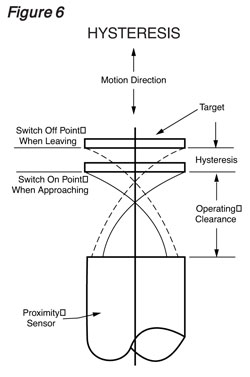
HYSTERESIS
Hysteresis is the switch-on point when the object approaches the sensor's active surface, and switch-off point, when the object is moving away from the sensor's active surface. Without sufficient Hysteresis, an Inductive Proximity Sensor would chatter (continuously switching on and off), so it is designed into the sensor circuitry. The differential travel (Hysteresis) is given as a percent of the expected rated operating distance Sr.; See Figure 6.
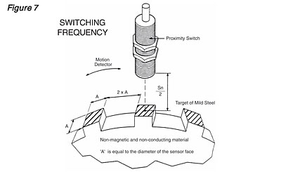
MAXIMUM SWITCHING
FREQUENCY
The switching frequency indicates the maximum number of switching operations of a sensor per second. The value listed in the product specifications is achieved with the conditions shown in Figure 7. The value is always dependent on target size, distance from sensing face and speed of target. Using a smaller target or space may result in a reduction of a specific sensor maximum switching frequency.
ACCESSORIES
Altech offers a full range of accessory products including quick disconnect cable assemblies, connectors, distribution boxes, etc. Please refer to each product specification in our catalog (PDF file).
CE MARK
GENERAL INFORMATION
The CE Mark is a compliance symbol, which means that the product meets the standards set by the European Committee for Electrotechnical Stan-dardization (CENELEC), and the Inter-national Electrotechnical Commission (IEC).
Products containing the CE mark are allowed to have free movement within the European Union (EU), and European Economic Area (EEA). Products manufactured in the USA that are exported to the EU and EEA should have the CE marking and utilize components also having the CE marking.
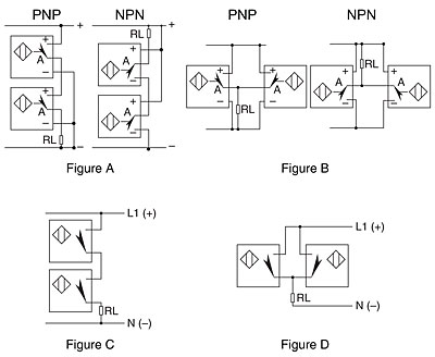
Series and Parallel Connection of Proximity Sensors
Series Connection of 3 and 4 wire DC switches (and Logic): Used when it is necessary to obtain two or more corresponding signals before an action is carried out. It is necessary to take into account the voltage drop Ud present at the output of each switch which will reduce the voltage available at the load correspondingly. (see figure A)
Parallel Connection of 3 and 4 wire DC switches (or Logic): Used when any one of the switches are required to activate the load. (see figure B)
Series Connection of 2 Wire AC and DC switches (or Logic): see previous note for Series connection of 3 and 4 wire switches. (see figure C)
Parallel Connection of 2 Wire and AC and DC switches (or Logic): It is necessary to take into account the cumulative no-load currents of each of the switches which would flow through the load in the unactuated condition of the switch. This could, under certain circumstances, trigger the load without actually operating the switch. (see figure D)
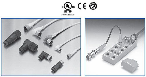
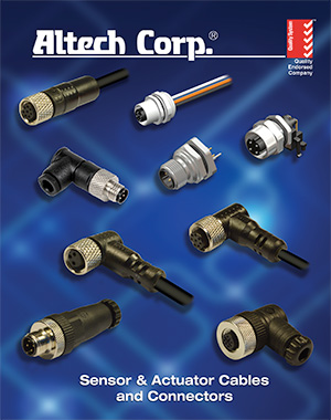
Connectors and Distribution Boxes
- Straight or 90° connectors
- M12 and M8 models
- PVC cable for standard applications
- PUR cable for moving applications
- Cable length up to 40 m
- Distribution Boxes with cable or to be wired
- UL/CSA approval
PVC cable connectors
These cables are suitable for medium mechanical stresses in a dry environment. They can be mounted on machine tools, packing machines assembly or productions lines. They can withstand oils, chemical substances and abrasion to a limited extent.
PUR cable connectors
These cables are intended for use in robotics, machine tools, metal working, assembly and production lines. They are made without silicone and varnish potted substances and they can withstand abrasion. The external sleeve can withstand oils and chemical substances and can bear the use of cable chains. The external sleeve is made through a co-extrusion process where the external part is PUR and internal part is PVC. Single wires are isolated with PVC.
Male/Female connectors to be wired
When manufacturing small series quanties or special tools, highly flexible cable solutions are neccesary. M8 and M12 connectors and cables,easliy meet this requirement. The angled model can rotate by 90°. Once connected, all the models comply with IP67 protection degree norms.
Male/Female cable connectors
The connection between the sensor and the distribution box is achieved through male/female cable connectors when the distance is shorter than 3m. These connectors can be straight or with a 90° angle, with PUR cable for moving applications. The cables are equipped with label holders, which allow easy marking.
Distribution boxes
Thanks to the wide range of distribution boxes and the relative connectors, you can make an easy, inexpensive, quick, versatile, IP67 protected installation. Altech can offer distribution boxes fully equipped with 5m cable for moving applications (PUR) or distribution boxes with quick and easy connection through spring cage terminal blocks.